A connection point is an object point that is used to link it with another object.
A line is a workspace object that determines correspondence between objects by connection points. Lines can be created with arrows at the end or without.
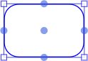
There are five basic connection points for workspace objects (except lines and polygons):
A line connected to such a point remains anchored to this point regardless of the object position. Central connection point is floating, that is, the link is anchored to one of the perimeter points depending on the object position.
To create a line between objects, do the following:
Activate the line creation mode. Select line type in the drop-down menu of the button containing a set of lines on the toolbar:
 . Straight line.
![]() . Arrow.
. Arrow.
 . Angular line.
 . Curved line.
NOTE. Line selection button looks like the last selected line type.
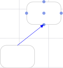
After activating any of modes, move the mouse cursor to one of the object connection points. The point size will be increased. Click and hold down the mouse button:
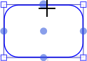
Then hold down the mouse button and move the cursor to the connection point of another object:
To create a connecting curved line, hold down the CTRL key when moving the cursor from the connection point of one object to the connection point of other object.
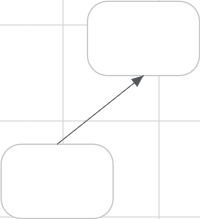
Release the mouse button. The line is built:
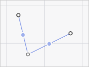
After a straight line/arrow is created, its center displays an additional point that can be used to create a broken line. To do this, drag the additional point located at the center of the line to the other place in the working area if it is required to create a broken line. Additional points are displayed at each new linear segment:
To remove the additional point, double-click the point.
NOTE. Lines can be created in any workspace place without linking to connection points.
See also:

 An example that shows the difference between perimeter connection points and the central connection points