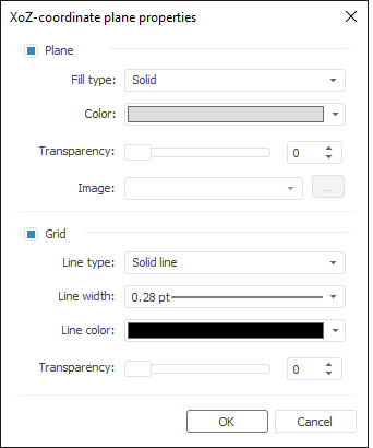
Use the Coordinate Plane Properties dialog box to set up coordinate planes:

Determine the following settings:
When the Plane checkbox is selected, coordinate plane is displayed in the scene. When the checkbox is deselected, coordinate plane is not filled. The checkbox is selected by default. When the checkbox is selected, the following parameters are set:
Fill Type. Select the Solid or Image fill type.
Color. Select fill color in the drop-down color palette. The parameter is available if the Solid fill type is selected.
Transparency. Select fill transparency in percents.
Image. Select an image in the drop-down list of previously loaded images or load an image to use as the fill. To load an image, click the ![]() button. A standard file selection dialog box opens. The parameter is available if the Image fill type is selected.
button. A standard file selection dialog box opens. The parameter is available if the Image fill type is selected.
When the Grid checkbox is selected, gridline is displayed on the coordinate plane. When the checkbox is deselected, no gridline is displayed. The checkbox is selected by default. When the checkbox is selected, the following parameters are set:
Line Type. Select line type: Solid Line or Dotted Line.
Line Width. Select line width. To set custom width, select the Custom item in the drop-down list, and enter the required value in the Line Width dialog box.
NOTE. Line width can be specified in different measurement units but the edit box always shows the value in points (1/72 inch).
Line Color. Select line color in the drop-down color palette.
Transparency. Set line transparency in percents.
See also:
 Plane
Plane